
Common Design Mistakes in Plastic Profile Extrusion
A plastic extrusion profile can look perfectly logical in CAD and still be difficult to manufacture. The reason is simple: extrusion is not just about reproducing a cross-section. Molten polymer has to flow through the die, leave the tooling in a controlled state, cool uniformly and retain its dimensions during calibration.
Many extrusion problems can therefore be traced back to decisions made before the extrusion die is manufactured. Uneven wall thickness, sharp corners, unnecessarily complex geometry and unrealistic tolerances can increase tooling cost, setup time, scrap and development cycles.
Why Plastic Extrusion Design Is Different
Plastic profile extrusion is a continuous manufacturing process. A polymer melt is pushed through a die that defines the cross-sectional geometry of the profile. Unlike machining, the material is not simply removed until the desired dimensions are achieved. Unlike injection moulding, the profile must continuously leave the die and then be cooled and stabilised.
This means that the geometry of the profile directly influences melt flow, pressure distribution, cooling behaviour, shrinkage and dimensional stability.
1. Uneven Wall Thickness
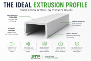
One of the most common mistakes in plastic profile extrusion is designing large differences in wall thickness without considering their effect on flow and cooling.
Thick areas generally retain heat longer than thin sections. At the same time, differences in resistance through the die can create an unbalanced flow pattern. After the profile leaves the die, different cooling rates can contribute to warping, twisting, bowing or dimensional drift.
What can happen?
- Uneven material flow through the die
- Different cooling rates across the profile
- Warping, twisting or bowing
- Longer setup and stabilisation times
- Difficulty maintaining dimensional tolerances
- Higher material consumption than necessary
2. Designing Sharp Internal Corners
A 90-degree corner may look harmless on a technical drawing, but sharp corners can be problematic in extrusion.
Internally, sharp corners can influence melt flow and create areas where material experiences higher local stresses. In the finished profile, they can also act as stress concentration points, particularly in materials that are sensitive to notches. Rounded corners generally improve flow and reduce stress concentration.
Sharp corner
Sharp internal corners can increase local stress and complicate material flow.
Rounded corner
A suitable radius creates a smoother transition and can improve both manufacturability and profile durability.
As a general principle, the corner radius should be selected together with the nominal wall thickness and material. A radius around the wall thickness is often a useful design direction, although the optimum geometry depends on the actual profile and tooling.
3. Making the Profile More Complex Than Necessary
Modern extrusion technology can produce surprisingly complex plastic profiles. That does not mean that every feature should be incorporated into the extrusion cross-section.
Deep narrow cavities, multiple hollow sections, isolated thin ribs and difficult undercuts can make flow balancing and calibration considerably more complicated. Complex geometry can also increase tooling cost and make process adjustment more sensitive.
4. Using Thick Sections Instead of Structural Geometry
When engineers need more stiffness, a common instinct is to simply make the profile thicker. In extrusion, this can create a new set of problems.
Thick sections cool differently from surrounding thin sections and can increase material usage, cooling requirements and dimensional instability.
In many designs, stiffness can be increased more efficiently by using ribs, returns, channels or other structural features while keeping the basic material distribution balanced.
| Design approach | Potential issue | Better question to ask |
|---|---|---|
| Make the entire wall thicker | More material, longer cooling and potentially greater distortion | Can stiffness be achieved through geometry? |
| Add a very thick local section | Creates an unbalanced section | Can the transition be distributed more gradually? |
| Add structural ribs | Can still create local flow and cooling effects if oversized | Can the rib be kept proportional to the nominal wall? |
5. Designing Deep, Narrow Cavities
Hollow plastic profiles are one of the major advantages of extrusion. However, every additional cavity creates another flow path that has to be filled, cooled and calibrated.
Particularly deep and narrow sections can become difficult to manufacture reliably. The issue is not simply whether the die can be machined — it is whether the polymer can flow through the geometry consistently and whether the resulting profile can be cooled and calibrated without distortion.
6. Specifying Unrealistically Tight Tolerances
Another frequent mistake is applying machining-style tolerances to an extruded plastic profile.
Plastic changes dimensions as it leaves the die and cools. Material shrinkage, temperature, extrusion speed, calibration, tooling condition and profile geometry all influence the final dimensions. Consequently, extrusion tolerances need to be defined according to the material, geometry and manufacturing process.
General tolerance ranges can be useful during preliminary design, but critical dimensions should always be reviewed with the extrusion manufacturer rather than copied blindly from a generic tolerance table.
Everything critical
±0.05 mm on every dimension may look precise on a drawing, but not every dimension needs this level of control.
Functional tolerances
Identify which dimensions actually affect assembly, sealing, movement, strength or performance — and assign tighter tolerances only where required.
7. Ignoring the Cooling and Calibration Stage
The extrusion die creates the basic shape, but the die does not create the final dimension by itself.
After leaving the die, the hot profile must be cooled and stabilised. Calibration systems, vacuum calibration, cooling tanks, haul-off speed and process temperature can all influence the final geometry.
This is particularly important for large, hollow or asymmetric profiles where different parts of the section may respond differently during cooling.
8. Designing Without Considering the Material
A profile geometry cannot be separated from the polymer being extruded.
PVC, PE, PP, ABS, TPE, TPU and engineering thermoplastics do not behave identically during extrusion. Melt viscosity, shrinkage, thermal behaviour, stiffness and flexibility can all influence the practical design window.
A geometry that works well with one material or compound may require changes when the material is changed.
9. Designing the Profile Before Talking to the Extruder
Perhaps the most expensive mistake is finalising the CAD geometry and tolerances before discussing manufacturability with the extrusion supplier.
An experienced extrusion manufacturer can often identify relatively small geometry changes that make a major difference to die construction, material flow, cooling and production stability. Early DFM feedback can also prevent expensive tooling modifications later.
Plastic Extrusion Design Checklist
Before releasing a new plastic profile for tooling, review the following points:
- Is the wall thickness as uniform as practical?
- Are transitions between different wall sections gradual?
- Have sharp internal and external corners been replaced with suitable radii?
- Are deep or narrow cavities really necessary?
- Could some complex features be simplified or produced in a secondary operation?
- Is additional stiffness achieved without unnecessarily thick sections?
- Are tolerances based on actual functional requirements?
- Has the selected polymer been considered during profile design?
- Can the profile be cooled and calibrated reliably?
- Has the extrusion manufacturer reviewed the design before tooling?
Quick Comparison: Bad vs. Better Extrusion Design
| Common mistake | Typical consequence | Better design principle |
|---|---|---|
| Large wall thickness variations | Unbalanced flow and cooling | Keep walls as uniform as practical |
| Sharp internal corners | Stress concentration and difficult flow | Use suitable corner radii |
| Unnecessarily complex cross-section | More difficult tooling and calibration | Simplify the profile where possible |
| Very thick solid sections | Higher material use and slower cooling | Use geometry to achieve stiffness |
| Deep narrow cavities | Difficult flow and calibration | Review cavity geometry early |
| Machining-style tolerances everywhere | Higher cost and unnecessary complexity | Specify tolerances according to function |
| Material selected after geometry | Design may not suit extrusion behaviour | Select material and geometry together |
| Manufacturer involved too late | Expensive tooling modifications | Perform extrusion DFM before tooling |
Design for Extrusion, Not Just for CAD
The best plastic extrusion profiles are not necessarily the most complicated ones. They are profiles where geometry, material, tooling, cooling, tolerances and the final application work together.
A small change to wall thickness, a larger corner radius or a simplified cavity can sometimes make the difference between a difficult extrusion process and a stable production profile.
For this reason, extrusion design should be treated as a manufacturing engineering task from the beginning — not as a CAD exercise followed by tooling.
Have a Plastic Profile to Extrude?
Send STP Extrusion your drawing, STEP file or even a sketch of the required profile. We can review the geometry, material requirements, tolerances and manufacturability before the extrusion tooling is finalised.
Early design review can help reduce unnecessary tooling complexity and avoid expensive changes later in the project.
Discuss Your Extrusion ProjectFrequently Asked Questions
What is the most common plastic extrusion design mistake?
One of the most common mistakes is designing a profile with large variations in wall thickness. Uneven sections can create unbalanced material flow, different cooling rates, warping and dimensional instability.
Why should sharp corners be avoided in plastic extrusion profiles?
Sharp corners can create stress concentrations in the finished profile and can make material flow through the extrusion die less stable. Rounded corners generally improve manufacturability and durability.
Can complex plastic profiles be extruded?
Yes. Complex plastic profiles can often be extruded, but increasing geometric complexity can make die design, flow balancing, cooling and dimensional control more difficult.
When should an extrusion manufacturer be involved in the design?
Ideally before the extrusion die is designed or manufactured. Early DFM feedback can identify geometry, tolerance, material and cooling issues before they become expensive tooling changes.
What information should I provide when requesting a custom extrusion?
A technical drawing or 3D model, material or material requirements, critical dimensions and tolerances, application details, expected quantities and required profile length are useful starting points. An existing sample or photograph can also help.
Technical note: extrusion design guidelines vary according to polymer grade, profile geometry, tooling design and production conditions. Specific dimensions and tolerances should be validated for the individual extrusion project.
 English (UK)
  Slovenčina
  Deutsch
  Magyar
  Français
  Čeština
  Slovenščina
  Hrvatski
  Nederlands